Before I get into the first blog post for 2022, I would like to take the opportunity to wish everyone who follows the blog a belated happy new year.
HF Transceiver - Modulator
"High Performance AM, CW & SSB Modulator for the G6LBQ Irwell HF Transceiver"
In
this blog post, I cover work on the first of the transmitter modules for my Irwell HF Transceiver, a multi-mode modulator that is capable of SSB, AM and CW modes.
Given the modes of operation outlined, the project requires some form of double balanced mixer (Aka DBM) so I considered the following options:
- Diode DBM Mixer
- JFET/Mosfet DBM Mixer
- Transconductance Cell DBM Mixer (Gilbert Cell)
The Doubly Balanced Diode Mixer
The diode mixer is easy to configure as a double sideband generator and is a popular choice with radio hams in their home-brew projects. The simplicity, low cost and ease of construction make the Diode DBM modulator a worthy contender so it is worth taking a look at it in more detail.
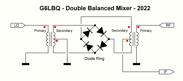
The following schematic illustrates the humble diode balanced mixer (DBM).
As you can see from the schematic, this mixer requires very few components and while it can be purchased as an off-the-shelf part, it can also be built with relative ease.
When building a diode ring mixer, care should be taken on the choice of components used in order to achieve good performance. The best diodes for the job are the hot carrier types commonly referred to as Schottky Diodes and ideally they should be matched.
Suitable Schottky diodes for building a mixer that are commonly available include; BAT42, 1N5711, BAT85, 1N5817, BAT48 & BAT46 just to mention a few. Small signal switching diodes like the 1N4148 and BAV21 can also be used but they do not perform as well as the Schottky diodes that, in general, have faster switching times, fast recovery and a quicker transition when going from the conducting to blocking state.
The easiest way to match the diodes is using a digital multimeter with a built-in diode test function. If your DVM does not have a diode test function, you can perform the same test using a voltage source and limiting resistor. The matching is done by testing diodes for the same forward voltage drop when biased to a forward current of 5 to 10mA like illustrated below.
For a more in-depth explanation of diode testing and matching, I highly recommend that you watch Alan Woke's YouTube video at the following web link:
https://www.youtube.com/watch?v=hYyzq4671nI
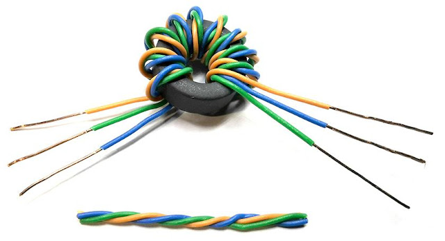
The diode mixer requires two identical transformers and these are typically made on FT37-43 ferrite toroidal cores. The construction of a transformer starts by preparing three suitable and equal lengths of insulated copper wire. The three wires are twisted together over their entire length. Next the twisted wires are passed through the ferrite core to form a coil of 10 turns. Note each time the wire passes through the centre of the core that is equal to one turn.
A picture is worth a thousand words so to illustrate the winding process, I have created a transformer using individual PVC coloured copper wires, though it is more common to use enamelled coated copper wire for the job.
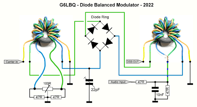
If you fancy building a simple diode balanced modulator, I have created a useful diagram that is easy to follow. It provides clear details on how to wire the transformers, which can often appear confusing, leading to building errors and failures.
From the above diagram, it can be seen that using the diode balanced mixer as a modulator requires additional components. The 100R preset and 47R fixed resistors form a parallel resistance of nearly 50 ohm and provide carrier balance adjustment. Ideally, a 50 ohm preset without the 47R resistors would be used here but they are not easy to source. The 22pF trimmer capacitor is added so that stray reactance can be tuned out to help improve the mixer's balance further. The components present at the audio input establish a 50 ohm match to the mixer as well as providing a degree of audio filtering.
It should be noted that the diode mixer ports do require a defined termination of 50 ohms and the simplest way of achieving this is to include a resistor, ideally, 50 ohms; however, this does increase the overall loss and efficiency of the mixer. A better way to terminate the ports is by the use of well-defined amplifiers and low loss diplexers.
Note
the fixed resistors shown in my
example are 47 ohm which is the nearest common value available, you could also
use 51 ohm though these are not as readily available.
There
are other types and configurations of diode mixers available but for the
blog I decided to explore the most common type, the +7dBm diode
balanced mixer, and, in particular, its configuration as a modulator.
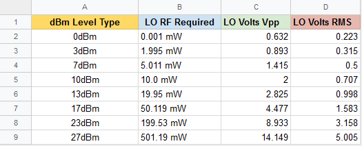
For your information and reference, I have produced the following chart that lists the different high-level mixers available based on their LO drive requirements.
Failure to provide the correct LO drive or matching to the mixer's ports will result in poor performance:
- Higher conversion loss
- Distortion
- Unwanted products
- Poor carrier suppression
- Incorrect diode switching
To conclude my look at the diode DBM as a modulator, let's take a look at the pros and cons.
Pros:
- Cheap to build
- Operates over a wide frequency range
- Good 3rd order intercept performance
- Good Port isolation, typically around 50 to 60dB
Cons:
- Requires a high level of local oscillator drive
- Inherent conversion loss of 5 to 8dB
- Requires matched diodes when built home brew
- Performance to easily compromised
J-Fet/Mosfet Mixer
There is not a lot for me to say regarding the use of JFET's or Mosfets in balanced mixer modulators. Whilst I am aware that it can be done, I am uncertain of how the carrier is suppressed and to what level so I will not pursue this option for the time being.
Transconductance Cell Mixer
The Transconductance Cell Mixer, more commonly known as the "Gilbert Cell Mixer" was developed by Barrie Gilbert in 1967. The wording "Transconductance Cell" is the name given to the transistor arrangement & topology.
The most common DBM devices based on the Gilbert Cell are the NE602 and MC1496. The NE602 was designed by an American electronics manufacture called Signetics and they produced another variant of the chip named the NE612. This was a product refresh to allow the internal oscillator to run at higher speeds but, in essence, they are the same. Just to confuse matters further, there is also the SA602 and SA612 but they are the same as their "NE" counterparts.
I cannot confirm when the NE602 was officially released but it would appear that both the NE602 and NE612 are now obsolete; however, the SA612 device remains current and is still available and a direct replacement for the other parts.
The MC1496 was developed by Motorola and released in 1972, it is still in production and in its 50th year of existence. It is available from all of the major component suppliers . I cannot help but wonder how many other Integrated Circuits have lasted for this length of time!
Motorola did allow other companies to produce the IC under license, including Philips, JRC and ON Semi. If you look at the image of the two ICs below, you can see they carry the ON Semi logo.
Out of the NE602 and MC1496, the latter is more suitable as a double sideband modulator and is therefore the device I have chosen for my project. When studying the device's data sheets, I came to the conclusion that the NE612 is not really intended for audio modulation and is better utilized as an RF mixer or demodulator with the caveat, its IP3 rating is not that great!
Before settling on the MC1496 for my modulator, I also considered DSP modulation using a MAX2452 quadrature modulator and a dsPIC33 device. Ryuu JA2NKD used these devices in his home-brew transceiver and it is something I am keen to try myself but for now I will go with the MC1496. The modular construction of my transceiver does allow for easy upgrades so I can change the modulator at a later date if required.
A Multi-mode Modulator for the Irwell HF Transceiver
My first port of call was to study the MC1496 data sheet and gain a greater understanding of the device's specifications and operating parameters.
The data sheet I downloaded is produced by ON Semiconductors and is dated October 2006 with a revision number of 10. The publication is extensive and spans over 17 pages, with many circuit examples, including one for AM modulation.
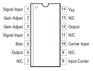
Rather than replicate the whole of the data sheet on the blog, I will convey the main features of the chip and the pin configuration.
Features
- Excellent Carrier Suppression up to -65dB @ 0.5 MHz & -50dB @ 10MHz
- Low intermodulation distortion
- Balanced Inputs and Outputs
- High Common Mode Rejection -85dB Typical
- Adjustable Gain and Signal Handling
- Ability to be configured for SSB, AM and CW modes
- Can be operated with dual or single DC supplies
Device PIN Connections
If you would like to read the data sheet in full, it can be downloaded from the ON Semi website at the following link:
https://www.onsemi.com/pdf/datasheet/mc1496-d.pdf
While the Data Sheet provides clear examples of using the IC, I decided to look at reference books & other transceivers to see how they implemented using the IC.
In the late 1980s, I owned a Yaesu FT-290R 2MTR multimode portable radio transceiver that had SSB and CW capability using the MC1496 device. Fortunately, I kept the schematic diagram and it has proven useful as a source of information.
My favourite reference book is "Experimental Methods in RF Design" by Wes Hayward W7ZOI, Rick Campbell KK7B and Bob Larkin W7PUA. This book is a treasure trove of information and a valuable asset to any avid home brewer. The book presents a great example of using the MC1496 in chapter six pages 6.56 & 6.57.
There is a wealth of information, including circuit diagrams and projects available on the internet that make use of the MC1496. I took the best of what I found and made a few changes and additions to suit my own needs and came up with the following ideas.
- Include a low-pass filter for the carrier oscillator, as my VFO does not have any filtering on the output ports.
Add separate FET switches for the AM and CW modes to facilitate the switching of individual carrier offset adjustments using preset resistors.
Include FET switching for TX/RX, PTT and CW operation.
Add a suitable amplifier to increase the RF output.
Add filtering to the audio input of the MC1496.
Include a 2nd method of generating CW with a colpitts crystal oscillator and buffer stage. This is just in case the carrier offset method does not work out!
In essence the MC1496 modulator will function as a double sideband generator with carrier nulling, AM and CW modes are achieved by applying a DC offset to unbalance the modulator and this is easily done with switching transistors and preset resistors.
I have decided to keep the microphone amplifier separate to the modulator and will add that later as a separate module. My intention is to build a conventional mic amp using an op amp with filtering, a switchable speech processor and VOX.
Here is the schematic diagram for my modulator module:
 |
| Click to enlarge to full size! |
A double sided printed circuit board was designed and professionally manufactured and this is shown unpopulated below:
 | ||
| Top view of modulator PCB measuring 92mm by 72mm |
 | |
|
I have carried out preliminary testing of the modulator, which shows excellent results. All of the switching functions work and the carrier offsets allow me to unbalance the modulator and control the carrier.
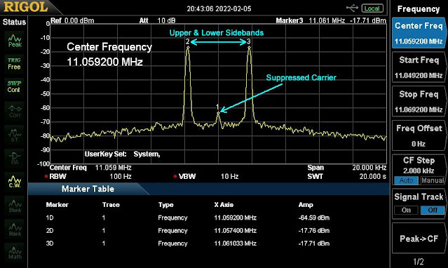
I used one half of my Two-Tone Generator to feed a 1.8kHz sine wave into the MC1496 audio input, I then fed the BFO port with an 11.0592 MHz signal. Good carrier suppression was achieved, as can be seen in the following image captured from my Spectrum Analyser:
In the image you can see the two sidebands generated from the 1.8KHz tone signal. The carrier has been suppressed to almost 47dB. This falls inline with the data sheet carrier suppression vs frequency plot:
I am pleased with the modulator module and will test it further once the transceiver build progresses but for now...
Project files will be made available via the Groups.io platform by joining my G6LBQ community group, where you can discuss my projects, ask questions and help others.
Joining my group is free. Just click on the button below.
Until next time...









Dear Andy , Excellent Job , 73s AP2RF
ReplyDelete