My last blog post was made on the 10th July 2022, which is just a tad over four and a half months ago. Traditionaly, I do not spend a lot of time during the summer months working on homebrew projects but now that autumn & winter are here, it is time to melt some solder again and play catch up!
Before I continue, I should explain the meaning of the banner featured above!
During the summer months of this year, I exchanged a few emails with a fellow radio ham Dave, who is located in central London. The emails were related to an SDR transceiver project we had both shared an interest in. During the email exchanges, Dave happened to mention he was a retired software engineer, which led to me telling him about my Irwell HF Transceiver project and my experience (or lack of) working with the Arduino platform to develop the VFO software for my transceiver.
To cut a long story short and fast forward a few months, I have had the great pleasure of spending time with Dave, either on the telephone or via Zoom sessions, which has resulted in the development of new software for my Irwell Transceiver project.
The new software written by Dave includes a menu system and the code has been streamlined to make adding new features or making changes manageable.
I am extremely grateful for the time Dave devoted to the software, not to mention the benefit of his professional knowledge. The new software took longer to develop than I think Dave or I envisaged and this was probably due to myself moving the goal post but also Dave's persistence to optimize the code and rewrite some of the library files being used.
Those of you who have followed the development of my Irwell HF Transceiver will be aware of the articles I have written on the VFO and my endeavours with software coding. My apparent success in adding software code for controlling multiple SI5351 devices and the switching of band-pass filters was functional, however, I have since learned that my code whilst functional is a good example of how to write bad code!
The software side of the transceiver development has always been a sticking point for me and a contributing factor in the length of time the project is taking to reach fruition but thanks to Dave's work, the project can move forward and the end goal reached.
Working closely with Dave on software development took me on an exciting journey into the world of software coding, where I learned a lot and this leads me back to the banner which heads this blog post. On the 19th of November, Dave set out on his own 22-day adventure leaving London and heading off to New Zealand, where he will backpack around 500km along the famous "Te Araroa" trail.
Dave, I wish you good luck on your adventure and I dedicate the banner to you :)
I will present the new software on the blog in more detail soon to coincide with some hardware changes and additions that benefit from it.
During my absence from the blog this summer, I did find time to complete another module for my Irwell HF Transceiver project, an interface for Digital Modes.
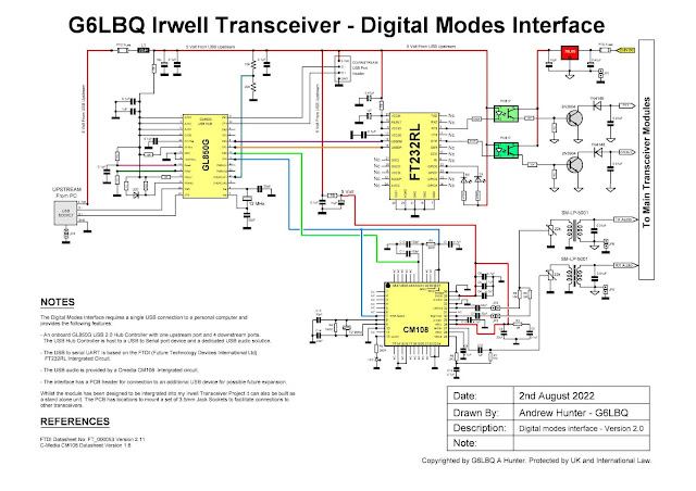
The interface module contains the following key integrated circuits:
- CM108 audio chip with integrated USB interface, DAC and ADC
- FT232 USB to Serial UART chip
- GL850G USB 2.0 Hub Controller
The devices chosen are all low-cost parts typically found in computer hardware and accessories.
The
inclusion of the GL850G USB Controller provides USB connectivity to the
CM108 and FT232 integrated circuits; it then facilitates a single USB
cable connection from the interface module to a personal computer carrying both
the audio signals and com port data, thus avoiding cable clutter.
To avoid ground loops between the transceiver and personal computer audio isolation transformers are used in the AF signal paths and optical isolators for signal switching. As an additional measure, common ground for analogue and digital circuits can be fully isolated via a set of pin header jumpers. It should be noted that the measures outlined also provide good protection against RF getting back into the transceiver the actual interface or personal computer.
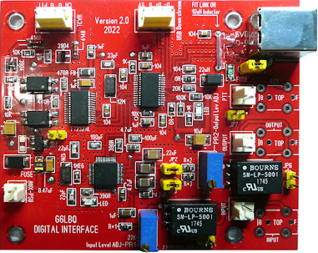
I laid out a PCB for the module and had a small quantity manufactured from a fabrication plant in China. The finished board is shown below after being populated with components:
 |
| Actual PCB Size is 90mm by 75mm |
Below the USB socket (top right of PCB) you can see three Molex connectors marked PTT, Output & Input, these are the connectors for interfacing to the Irwell HF Transceiver.
The interface can also be built and housed in an enclosure to form a standalone digital & CW mode interface. The PCB has provisions for mounting three 3.5mm jack sockets to facilitate connections to other transceivers.
Finally, here is the schematic for the G6LBQ Digital Mode Interface:
 |
| Click image to enlarge to full size! |
I have carried out some preliminary tests of the interface on the Irwell HF Transceivers receiver and it is working well and, as expected, tests on the transmitter side will have to wait until a later date pending completion of the transceiver.
As usual project files will be made available via the Groups.io platform by joining my G6LBQ community group, where you can discuss my projects, ask questions and help others.
Joining my group is free. Just click on the button below.


No comments:
Post a Comment
I appreciate your comments on the blog content, however the blog has been subject to idiots trying to use the comments facility as a means to post advertisements & spam so all comments are now approved and moderated.