Welcome to part 6 of my Allstar Link node build.
In
this instalment the project finally comes together with the boxing up of all the various modules and parts that I covered in my previous blog posts.
Choice of enclosure
To enclose the project, I decided that I wanted to keep everything screened to minimize the possibility of unwanted interference in the shack. You may remember in part 4 of my build I commented that there's a reason computers are built into metal boxes!
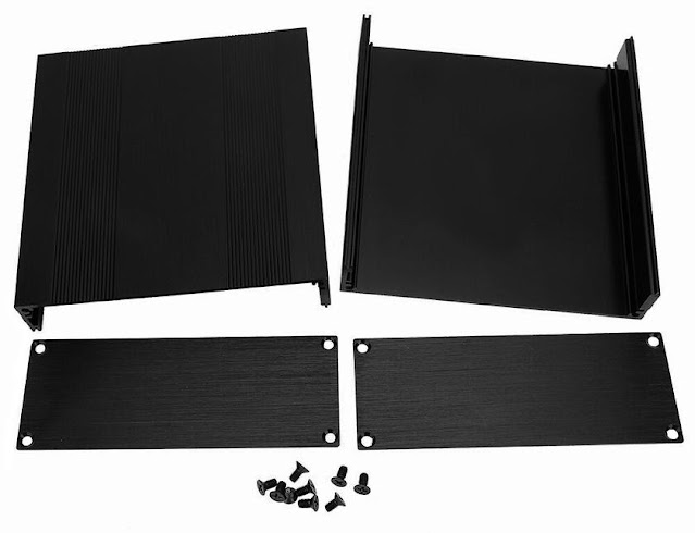
The enclosure I chose is a split body extruded aluminium type, as shown below.
The dimensions of the case are 54 by 145 by150mm. I purchased mine from eBay and paid just under £15 for it delivered.
If the above web links are no longer valid just search on Google with the following "Aluminum Enclosure 54x145x150mm" and you should find a few suppliers listed.
Options for high or low RF output power
Before proceeding any further, a decision needs to be made regarding what
the final RF output power from the node will be. By default the radio
is capable of producing around 4 watts of RF output. Taking into account that the node
will operate with a high transmit duty cycle, it is necessary to reduce
the RF output to a safer level to avoid damage.
Option 1: For low power 20 to 40 mW you do not need to fit the Buck Converter module or drill the associated mounting holes; however, a further modification must be made to the Baofeng BF888 to reduce the RF output to a lower level. The modification involves the removal of the main RF output transistor, this is then bypassed using a capacitor or wire link. For further information on this modification please take a look at the following web link: 888 Low Power Modification
Option 2: For high power 100mW or above, you will need to fit the Buck Converter module and drill the associated mounting holes.
For
now I will continue with the casing up based on using option 2. I will
cover the transmit output power in more detail later once everything
is mounted in the enclosure and wired up.
Template for drilling the bottom of the case
All of the main electronics are mounted on one half of the case and from now on, I will refer to it as the base.
I produced a drilling template for the base in CorelDRAW; this allows me to replicate the drilling process and share my layout as an aid for other node builders.
Below is an image of the template I created but please note it is not to size.
 |
| Click to enlarge to full size! |
If you want to print a template from the above image, click it so it displays full size, then save it to your computer and use your favourite graphics programme to print a copy out. The file is a standard PNG type and should be printed at 100% size, resulting in an image that is 129mm by 150mm. If you would like a copy of the template in PDF format, please message me using the contact form at the top of the web page.
Cut out the template and make sure it sits flat at the bottom of the case as per the illustration below.
If the template fits correctly, there should be no side play movement. To avoid the template sliding in a front to back direction, secure it in place with Sellotape or masking tape along the front and back edges. I recommend that you use a centre punch to make shallow indentations in the aluminium and remove the template prior to drilling.
Drill the fixing holes as per the template and your preferred RF power option. Start off with a small 1-mm-drill bit and increase the drill bit size gradually to get the needed hole sizes. The drilled base (option 2) should look like the one in the image below.
For mounting the modules, you will need some PCB standoffs.
8 of M3 thread type - female to female - 8 to 10mm in length
2 of M2.5 thread type - female to female - 8 to 10mm in length
I used brass types but you could also use the steel nickel-plated variety; I would, however, avoid using the nylon nonconductive type, as these could cause issues with PCB grounding.
The two M2.5 PCB standoffs were used on the LM317 module and the M3 size on the rest of the modules.
Offer the PCB standoffs to the respective module mounting holes and check to see if the standoffs have clearance from nearby PCB tracks or components, if needed, use insulating washers between the standoffs and module mounting holes.
All the modules in place
Here is an image showing all of the modules in place, securely mounted and ready for wiring up. Note the USB sound module is not shown in this image; it simply plugs into one of the Raspberry PI USB ports.
Wiring the Modules
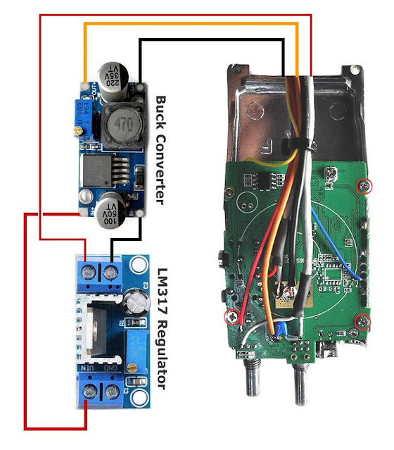
Connect the red, orange and black wires from the Baofeng radio to the modules as illustrated in the next image. Next fit additional wire links between the buck converter module and the LM317 voltage regulator module. If you prepared the radio with different coloured cables to the ones used in my example, care should be taken to ensure the cables are connected to the correct points!
If you have opted to build the low-power version of the node and omitted the buck converter module wire as follows.
Here is an image of all the modules mounted to the base of the enclosure and wired up ready. Note the CM108 sound module is plugged into the bottom USB port (top left in the image). It is then secured in place with an end stop made from 1.5mm thick angled aluminium size 20mm by 20mm. Use the two remaining holes in the base of the enclosure to mark up the angled aluminium ready for drilling. Drill the holes with a 3-mm-drill bit and secure in place with M3 fixings.
Front Panel
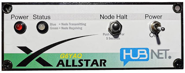
I produced a front panel label in CorelDRAW then printed it onto photo quality paper with my inkjet printer.
The label is used as a template to mark the drill holes prior to drilling. Once all the holes are drilled, the 4 corner screw holes on the label must be cut out carefully with a small sharp craft knife. This is a tricky job, as the holes are close to the edge of the paper.
The label is fixed to the front panel using "3M Spray on Display Mount Adhesive" available from the likes of Amazon & eBay. Allow sufficient time for the adhesive to dry then trim out the holes for the LEDs and switches.
Here is an image of the front panel with the label fixed in place and the LEDs and switches mounted. The text placement under the switches could do with lowering a little but I am otherwise happy with the end result.
If you would like a printable copy of the front panel with your callsign on please message me using the contact form at the top of the web page and I will send you a copy via email in PDF format.
Wiring the front panel
Using the diagram below, wire up the front panel controls and LEDs. Care should be taken to ensure the cables are connected to the correct points, especially if you have used different coloured cables to me!
NOTE The wiring points shown are correct for the Raspberry PI 3B plus model, if you are using an earlier or later model of the PI, the connections may be different!
Wiring the antenna socket
I decided to re-use the original rubber duck antenna and socket from the Baofeng BF888. The socket is mounted on the top half of the enclosure using a 150mm length of RG316 coax cable. Here is a picture of the cable soldered to the socket and the free end prepared ready for connection to the radio.
Before the coax cable can be attached to the radio, a small amount of the green solder mask must be removed from the PCB close to the antenna connection point to forms a ground connection point.
The following image shows the coax cable soldered in place on the radio.
Back panel
Before the wiring can be completed, the enclosure back panel needs to be prepared with holes cut for the DC power and ethernet network socket.
I have produced a template for the back panel in CorelDRAW. Click the image below to make it full size, then save it and print to 100% size.

Click To Enlarge Full Size!

The square hole for the network socket can be formed by drilling a series of holes to remove most of the unwanted aluminium then finishing it off with a small file.
The network socket/extension cable that I used is branded iGreely and is 1ft/30cm in length. They are supplied in a pack of 2 and are available from Amazon at the following web link
https://www.amazon.co.uk/iGreely-Female-Ethernet-Network-Extension/dp/B06Y4J9MZ4/
If you carry out a search on Google with the text "iGreely 2Pack RJ45 Male to Female Screw Panel Mount" you will find lots of suppliers for the cable.
Remaining Wiring
To complete the wiring connect the remaining power supply cables, as shown in the diagram below.


