HF Transceiver Audio Amplifier Module
"A Multi-mode Audio Subsystem for the G6LBQ Irwell HF Transceiver Project"
As I mentioned in my previous blog post, I have been developing a high-performance HF multi-mode radio transceiver based on a series of modules that can be upgraded or improved over time.
For this blog post, I present my multi-mode audio amplifier subsystem, which handles the receive audio for the various modes of operation.
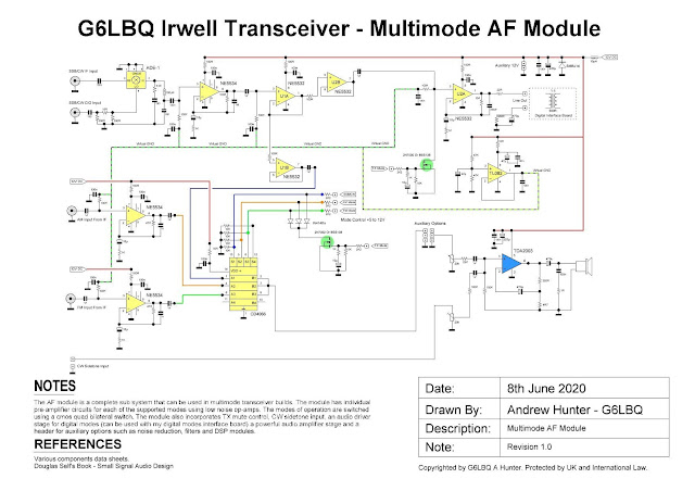
Here is the schematic diagram for the module.
 |
Click image to enlarge to full size! |
As can be seen from the schematic diagram, each mode of operation has its own dedicated low noise NE5534 preamplifier stage, the SSB and CW preamplifiers are preceded by a diode ring mixer to demodulate signals from the IF amplifier.
A further two dual operational amplifier ICs type NE5532 are used as buffers and a line driver for connecting to my digital mode interface. which I will cover in another blog post soon.
The remaining operational amplifier IC is a TL082 JFET that acts as a virtual ground for the NE5534 and NE5532 devices.
Mode selection is handled by a 4066 quad bilateral CMOS switch IC. This connects the low-level audio signals to a powerful TDA2003 power amplifier IC. During transmit a 2N7002 FET transistor turns off the 4066 switches, thus muting the audio to the TDA2003 amplifier.
In CW mode a sidetone input provides live audio monitoring of the Morse code being sent complete with adjustable gain control.
Finally provisions have been made for connecting auxiliary devices to the module, such as audio filters.
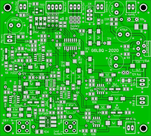
I drafted up a PCB for the module, which you can see in the exported CAD image shown below.
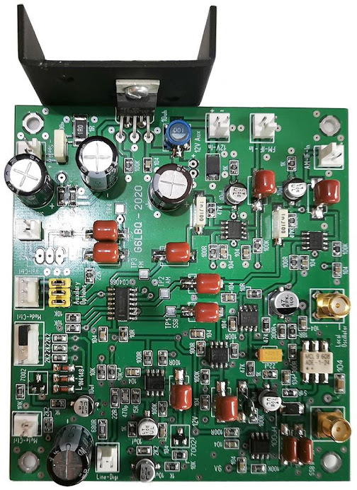
And here is a PCB fully populated in all its glory :)
 |
| Actual PCB Size Is 100mm by 90mm |
Project files will be made available via the Groups.io platform by joining my G6LBQ community group, where you can discuss my projects, ask questions and help others.
Joining my group is free. Just click on the button below.


Hi Andy,
ReplyDeleteThe Irwell modules are very interesting, thanks for sharing these. I've been studying the Audio module.
It appears that all of the preamp gain is via U1 NE5534, which includes filtering. I am not smart enough to recognise what the textbook configuration is for this stage. Can you please provide indicative bandpass for these values?
I am also wondering why U1A and U1B (NE5532) are needed. U1A is configured as a voltage follower to give high input impedance and low output impedance (i.e. a buffer), but why follow it with a second op amp? Are two better than one? Was it a small gain for no extra parts, given one was available in the dual package?
On the use of the 4066 audio switch as a mute, I've tried a number of options to silently mute a CW receiver with TDA2003 and most have fallen short. I am after a noiseless T/R and R/T transition. As well as muting, which is the main function, would you say the 4066 is silent?
Thanks very much for your design work. 73 Paul VK3HN.
73 Paul VK3HN.
Hi Paul
ReplyDeleteThe NE5534’s provide the gain for the various IF modes.
>>You asked why U1A and U1B are needed and are two buffers better than one
U1A and U1B split the audio path for the USB/LSB and CW modes of operation to the main TDA2003 audio amplifier and the line output driver so one buffer for each signal path.
U1A is proceeded by a further buffer stage U2B so yes there are two buffers and to answer your question NO two buffers are not better than one but, in this case, they serve a purpose.
As already mentioned, U1A and U1B split the ssb/cw audio path but that is not there only job! For digital modes I want the audio to go to U2A the line output driver but not the TDA2003 audio amplifier. For digital modes silence is golden 😊 so by muting U1B we don’t have to listen to the digi modes racket and it just gets passed onto the line driver stage via U1A & U2B.
So why proceed U1A with U2B? The answer is simple, muting. I can mute the line stage independently of the USB/CW audio path.
>> You asked about the 4066 switch and in particular if it was noiseless during switching
The answer is yes.
>> You asked if I could provide indicative bandpass values for the NE5534 pre-amp?
I modelled the pre-amps in Spice simulation and when I get some spare time I will re-visit the files and post an update to the blog post with further information.
>>You asked, can you explain the meaning of virtual ground?
In general Op-Amps are designed to run from dual supply rails but in my circuit they operate from a single supply rail, the virtual ground serves to bias the op-amps halfway between ground and the single supply rail.
Thanks Andy for your detailed explnanations. Very useful!
ReplyDeleteAs I understand it, U1A is a unity gain common buffer/driver, which drives audio to each of U2B (digital path) and U1B (SSB/CW path). U1B seems redundant (it provides no additional gain, signal shaping, and is not directly muted) but it may help to see it as providing symmetry.
Of course, the op amp non-inverting inputs need a Vcc/2, silly me! Why use an op amp (TL082) for this instead of just splitting Vcc with two 10k resistors?
I'm going to build this for a CW receiver audio stage so i won't need the extra sources or the digital output, I'm attracted to it by the promise of nice clean T/R muting.
Thanks Andy, your Irwell project is of real interest to me.
73 Paul VK3HN.