HF Transceiver - Receive Pre-Amplifier Module
"A look At RF Preamplifiers For The G6LBQ Irwell HF Transceiver"
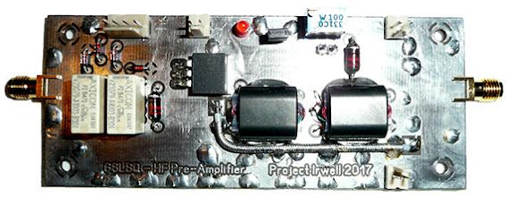
In this blog post I take a look at RF Preamplifiers and build a suitable module for my Irwell HF Transceiver project.
The RF preamplifier is one of the most important stages in a receiver and it has to meet certain criteria in order to cope with the vast range of signals available at its input. A poorly designed RF Preamplifier can destroy a receiver's overall performance so care must be given to the implementation of this stage.There are several key points to consider when choosing or designing an RF PreAmplifier:
- How much gain is needed.
- The range of signals that can be present within the amplifier before problems occur.
I will not be covering the 1dB compression point, as I do not feel this is as important as the linearity of a small signal amplifier.
Looking at gain first and how much is needed. There is a misconception that the more you have of something the better off you are but this is not true when looking at RF Preamplifiers. The weakest discernible signal that we can hear from a receiver is that limited by noise. The noise in a receiver originates from two sources: thermal noise generated from the electronic circuits and in-band noise picked up via the receiving antenna.
There is a case in point that RF Preamplifiers can do more harm than good. This is true in some cases, however, for some radio frequencies, there is a need for these amplifiers, especially for operation on VHF, UHF and microwave frequencies. For the HF bands, things are a little different, especially at the lower frequencies, where atmospheric noise is more prominent and in-band interference from power lines and electrical products blights the airwaves.
I
personally do not use an RF Preamplifier for frequencies below 7MHz as this is where atmospheric and man-made noises prevail the most. Think about the following scenario and all should become clear why I do not use an RF Preamplifier below 7MHz
I am listening to a weak station on 3.7 MHz and just about able to hear it above the atmospheric and man-made noise levels, I switched on the RF Preamplifier built into my radio and the level of the noise increases yet the station I am listening to has not improved and if anything is less intelligible, why is this?
Answer: By Switching on the RF Preamplifier I have not only amplified the atmospheric and man-made noises, I have also introduced additional noise that is inherently generated by the Pre-amplifier's own electronics; thus the station being listened to is now buried deeper into unwanted noise. It should also be noted that with the Pre-amplifier on there is the potential to overload the receiver and create unwanted distortion!
So with respect to "how much gain is needed", the answer is simply none or as little as is needed. This of course depends on the frequency in use and other factors, such as antenna & location.
A good way to test whether you need an RF Preamplifier in circuit is to simply disconnect the antenna from the radio then reconnect it, on reconnecting if you can detect an increase in band noise, you probably don't need the amp in circuit.
Next we need to consider the range of signals that can be present within the amplifier before problems occur. The airwaves are full of signals that fall within the pass band of a receiver and others referred to as out of band. These signals all have the potential to create intermodulation distortion or IMD for short. IMD in an RF environment is the combining of undesirable signals with wanted signals that produce distortion.
In order to reduce out of band signals, good filtering must be introduced between the antenna and RF amplifier input. I am not going to cover the filtering in this blog post as it is a topic of its own that I will cover later when I present my band-pass filter modules for the Irwell Transceiver.
The following image provides an illustration of the band-pass filter and how it protects the amplifier from out of band signals.
Removing out of band signals and only allowing wanted signals through to the RF Preamplifier helps reduce the probability of intermodulation distortion. It does not, however, eliminate IMD so other measures need to be taken to ensure possible IMD is managed to a minimum. Multiple strong signals within the receive pass-band can still combine and produce IMD!
My explanation of IMD has been kept to a minimum, though it should be noted that this is a complex subject with different magnitudes and orders that are beyond the scope of my blog.
For the best chance of keeping IMD products to a minimum, my RF Preamplifier will need to have high immunity to overload and good linearity. This will require a reasonable amount of bias current, therefore dictating the choice of semiconductor device used. As I do not intend to use the preamplifier on all of the HF bands It will need to be switchable and either in circuit or out. Also as an additional measure for dealing with problem signals some form of switchable attenuation must be incorporated at the amplifiers input.
As already outlined, you can have too much gain so I will aim for around 10dB and work on the principle "less is more" :)
There
are different semiconductor devices and configurations to consider for the
amplifier but in terms of component choice, all contenders will utilize some form of dedicated RF device for amplification. This could be an FET, bipolar transistor or a monolithic chip device.
I have experimented with monolithic amplifier devices which offer the advantage of requiring very few additional components to function, they also offer the added benefit of being internally matched to 50 ohms.
Here's a HF Monolithic Amplifier I designed based on the Mini-Circuits GALI-74+
 |
| Top view of PCB |
 |
| Bottom view of PCB |
The amplifier contains two GALI-74+ devices operating in a balanced configuration, this has the benefit of canceling out the even harmonics. The manufacture data sheet quotes the following features for the devices at an operating frequency of 0.1 GHz
- High Gain of 25.1 dB
- IP3 of +38 dBm
- Noise figure of 2.7 dB
- Output Power @ 1dB Compression point 19dBm
- Output IP3 @ 0.1 GHz is 38 dBm
Whilst the amplifier performed unconditionally stable, the gain was excessive for my particular needs. The device is probably better suited to VHF & UHF applications. Also I am not convinced that the quoted 2.7dB noise figure and +38 dBm IP3 specifications extend down to HF frequencies so I won't be using this particular amplifier in the Irwell HF Transceiver project.
If you are wondering what IP3 is, it's an acronym for Third-Order Intercept, which in technical terms refers to spurious output signals generated at harmonic frequencies from a fundamental frequency or signal. The IP3 measurement is the point at which the fundamental and third order products are equal in power. I will be looking at IP3 in more detail once my Irwell HF Transceiver is complete and I look to quantify its performance.
Another RF Preamplifier I would like to try out is the high performance Norton transformer feedback design pioneered by Dr. David E. Norton. My initial research shows that the amplifier ticks all the right boxes and is an excellent choice for high performance receivers but before I contemplate building one, I want to carry out more research on the design and gain a greater understanding of its operation and component choices.
A good point of call for inspiration when considering options for a high-performance transceiver is the Sherwood Engineering website. Here you will find some interesting presentations along with tips and receiver test data that rank commercially available transceivers.
I used the test data ranking on Sherwood Engineering's website to form a list of commercial transceivers that I was interested in looking at. Using the Google search engine, I was able to locate and download schematic diagrams for the transceivers and study their receive front end designs. I was drawn to the receiver front end of the Elecraft K3, as this encompassed everything I had outlined and was looking for, it also appeared reproducible as a module.
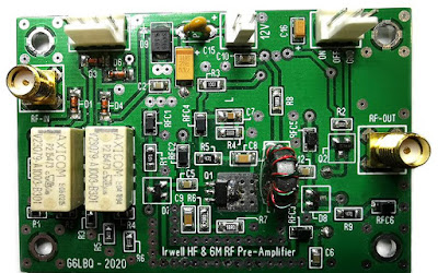
As a stop gap before I contemplate building a Norton amplifier, I decided to, in essence, clone the Elecraft K3's front end amplifier. Thanks Elecraft for making the technical schematic diagrams available!
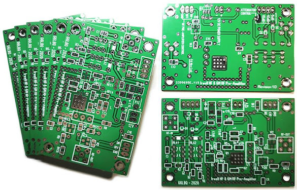
I designed a PCB for the amplifier and had a small batch made, which unpopulated look like this:
 |
Actual PCB Size is 75mm by 50mm |
 |
| Actual PCB Size is 75mm by 50mm |
The amplifier worked the first time, which is to be expected given it originates from an impressive pedigree. Thanks again Elecraft!
The schematic diagram for my RF Preamplifier is shown below
 |
Click image to enlarge to full size! |
The measured gain of the amplifier is just under 12 dB and in use it is proving to be a solid performer, especially when used in conjunction with my H-Mode mixer. My prototype receiver is currently in use on a daily basis and operated without front end band-pass filters and much to my amazement and delight I am experiencing no discernible IMD issues.
In the next blog post I will be presenting my Digital VFO, which, in effect, means we have a tried and tested set of modules to facilitate the build of a single conversion superhet receiver.
As usual project files will be made available via the Groups.io platform by joining my G6LBQ community group, where you can discuss my projects, ask questions and help others.
Joining my group is free. Just click on the button below.
Until next time...


No comments:
Post a Comment
I appreciate your comments on the blog content, however the blog has been subject to idiots trying to use the comments facility as a means to post advertisements & spam so all comments are now approved and moderated.