HF Transceiver H-Mode Mixer Module
In
this blog post, I present details of my high performance H-Mode RF Mixer stage.
The H-Mode RF Mixer is a high performance circuit and a module for my homebrew ham radio transceiver that I call the "Irwell".
The H-Mode mixer was designed by Colin Horrabin G3SBI with subsequent revisions published by Giancarlo Moda I7SWX and Martein Bakker PA3AKE. Full credit is acknowledged to Colin, Giancarlo & Martein for their extensive work and research on the H-Mode mixer.
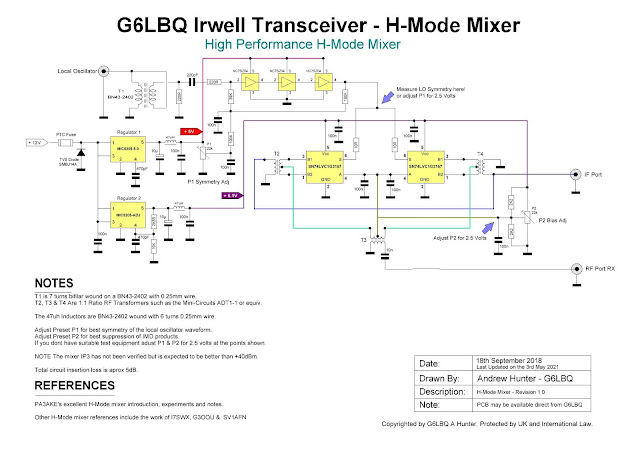
The H-Mode mixer gets its name from the letter "H" depicted in the transformer configuration, which resembles an "H".
During my research of the H-Mode mixer, I came across an interesting article by Bob Burns G3OOU, who used three individual NC7SZ04 TinyLogic high-speed inverters in the squarer, noting that the devices improved the VHF response and reduced power consumption above 50MHz
The NC7SZ04 is an inexpensive device and readily available from all of the major component suppliers for around 25 pence here in the UK. RS Components sell the device in packs of 10 so I ordered some, having decided that I would follow in the footsteps of Bob Burns for my own H-Mode mixer build.
Here is the schematic diagram for my version of the H-Mode mixer.
 |
Click image to enlarge to full size! |
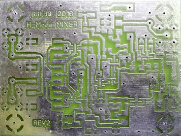
I drafted up a prototype PCB, as illustrated in the following image exported from my CAD design software.
 |
| Actual PCB Size is 70mm by 50mm |
Here is the prototype PCB after etching, drilling and tinning. Some of the drill holes are used for through hole connections by using short lengths of wire that are soldered to both sides of the board.
 |
| Not bad for a home-made PCB! |
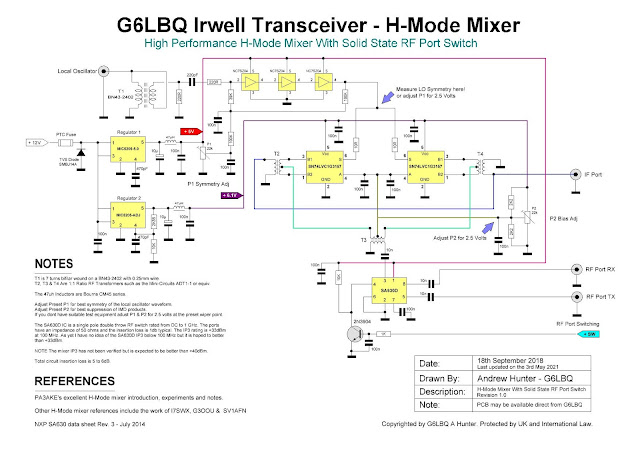
I have also produced a version of my H-Mode mixer with a solid-state RF switching device in the RF port, which can be used for TX and RX signal control. Note that the RF and IF ports are actually symmetrical so they can be used either way round. This basically means that the switching can be allocated to either the RF or IF as needed.
Here is the schematic diagram for my H-Mode mixer with RF/IF switching.
 |
Click image to enlarge to full size! |
I used a SA630D chip for signal switching. This device is rated to operate from DC to 1GHz with an input-output impedance of 50 ohms and an insertion loss of 1dB. The manufacture data quotes an IP3 of +33dBM at 200MHz so probably no the best choice for the HF bands. As I have a quantity of the SA630D in my parts stock, I decided to make use of them anyway.
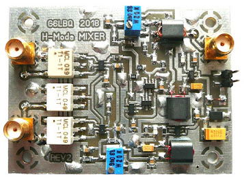
For this version of the mixer, I decided to get a batch of PCB's professionally manufactured. The following image shows a completed module.
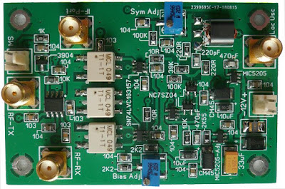 |
| Actual PCB Size Is 75mm by 50mm |
For now I have not made any meaningful tests to quantify the performance of my H-Mode mixers, though the performance is noticeably better than that of a diode ring mixer. I did carry out a quick comparative check on the output of my H-Mode mixer against that of a diode ring mixer and on my spectrum analyser the output of the H-Mode was much cleaner, displaying far fewer spurs than the diode mixer .
Once I complete the Irwell transceiver build, I will carry out tests to determine the actual end projects performance. This will involve building some additional test equipment and I will document this along with the performance results on the blog at a later date.
Project files will be made available via the Groups.io platform by joining my G6LBQ community group, where you can discuss my projects, ask questions and help others.
Joining my group is free. Just click on the button below.
Until next time...




No comments:
Post a Comment
I appreciate your comments on the blog content, however the blog has been subject to idiots trying to use the comments facility as a means to post advertisements & spam so all comments are now approved and moderated.