For part 1 of the BandPass Filter click here.
HF Transceiver - Band Pass Filter Module
"High Performance RF Band Pass Filtering for the G6LBQ Irwell HF Transceiver"
It has been almost a month since I posted a blog about the high performance RF Band-Pass Filter that was pending development for my Irwell HF Transceiver project. Fear not I have been busy in the background working on the BPF module and I can now provide a worthy update .
On the surface the band-pass filter appears a relatively simple circuit but when there are ten filters to be developed, the whole process becomes somewhat of a time sink and labour of love!
To recap, the filters need to cover 0.1 to 30 MHz with low insertion loss of 1dB or less and provide good harmonic suppression for the HF ham bands. The BPF design also has the ability to be usable in both the receive and low level transmit paths.
Having established that the BPF module was going to consist of ten individual filters, it soon became evident that the filter was going to require some real estate in terms of PCB space.
The design of the PCB was certainly going to be a challenge in order to shoehorn all of the components into as little space as possible. Here is a quick breakdown of the components count destined for the PCB:
50 of - T50 Style Iron Powder Toroid cores
160 of - NPO/COG Capacitors
22 of - Miniature Signal Relays
22 of - High speed switching diodes
4 of - SMA RF PCB Sockets
24 of - Brass PCB Mounting Pillars
2 of - Molex Connectors
20 of - IDC Connectors
It is evident from the component count that the BPF was not going to win any prizes for miniaturization, especially with 50 T50 toroid cores onboard. The T50 cores measure 12.7mm by 4.83mm so those alone take up a fair amount of space.
The T50 cores were chosen, as they provide a high Q and low loss, smaller cores like the T37 could have been used but they offer a lower Q factor and higher loss. Larger cores like the T68 variant could also be used and potentially offer a further improvement in performance but as the T50 cores are providing excellent results, I have not bothered to test the T68 cores.
I spent countless hours laying out a suitable PCB for the BPF module and after many attempts and fails, I settled on a design that uses a main-board PCB with plug-in daughter board PCBs for the actual filters so the completed BPF comprises of 11 PCB's in total!
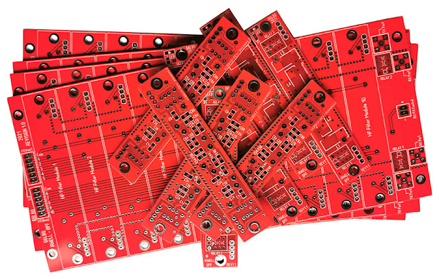
In mid September I ordered a batch of PCB,s which arrived in less than a week. They are shown in the following image:
The main-board PCB measures 207mm by 95mm so it has a fairly big footprint but as I am in pursuit of performance, the size is less relevant. The daughter boards measure a respectful 94mm by 18mm and connect to the main board using 2.54mm header plugs and sockets. The boards are secured in place using brass PCB pillars and M3 screws.
Over the last few days, I have been busy building up some of the filters and the next image shows the bottom of a daughter board populated with a set of capacitors:
 |
PCB shown larger than the actual size. |
Here is the same PCB with the top components fitted:
 |
| PCB shown larger than the actual size. |
Next is an image showing a top view of the main board:
 |
| PCB shown smaller than the actual size. |
Note the wire links located on the top of the main board. This is something I hate doing when designing a PCB but it was the only way I could route connections over the 50 ohm PCB transmission tracks and keep the ground plane above them intact. This could have been avoided but it would have been at the expense of a PCB with more layers.
The 50 ohm transmission lines reside on the bottom of the PCB, as can be seen in the next image:
 |
| PCB shown smaller than the actual size. |
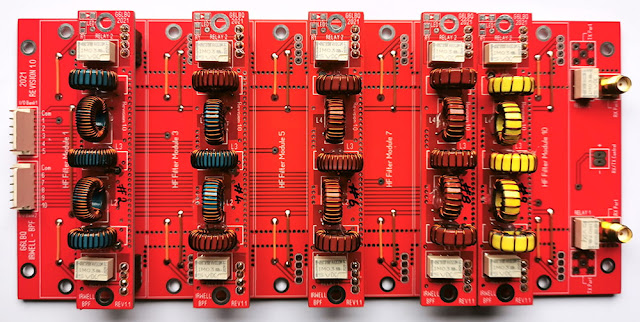
The final image shows the main board populated with five filters:
 |
| PCB shown smaller than actual size. |
So that is where I am up to with the BPF, I have five more filters to build and I need to fit the SMA RF connectors for the transmit path, make up the connecting cables and secure the filters in place with brass stand-offs, then the module will be finished and complete.
I have tested the five filters built so far on my spectrum analyser and they all perform as intended, the insertion loss is 1dB or less. Once I have finished the remaining five filters, I will produce a full set of plots from the analyser and post these with further project details on my Groups.io G6LBQ community group, where you can discuss my projects, ask questions and help others.
For part 3 of the BPF module, click here.
Until next time...


Thank you for providing this information. Few months ago, I was in desperate need of a band pass filter. Following an online search, I came upon the Anatech electronics website. I received all of my required band pass filters, as well as a request for a custom band pass filter, and received the best goods from them in a timely manner. You can also reach out to them if you require band pass filters.
ReplyDeleteAnatech is an interesting website and maybe the post is an advert for them!
ReplyDeleteAnyway as my blog is all about home-brew radio projects my intention has always been to build it myself and my BandPass filter is no exception.
Andy G6LBQ