For part 1 of the BPF module click here.
HF Transceiver - Band Pass Filter Module
"High Performance RF Band Pass Filtering For The G6LBQ Irwell HF Transceiver"
In this blog post, I conclude the development of my high performance RF Band-Pass Filter suitable for the Irwell HF Transceiver as well as SDR receivers and other transceiver builds.
The BPF module is almost complete with 9 of the 10 filters built and tested. The remaining filter requires some components that I have had to order in so rather than delay the concluding BPF blog post, I decided to bring the project to a conclusion and will add the last filter once I receive the parts ordered.
Since the last blog post, I have spent many hours winding toroid cores as well as measuring capacitors and cherry-picking the best of the bunch but more on that after a look at the BPF schematic.
 |
Click to enlarge to full size! |
The schematic diagram above represents one filter sub module, all the other filters are identical apart from the component values required per filter. You will notice that there are no adjustable components for tuning the filters so the components used must be close tolerance types.
For my own build, I was going to purchase 1% tolerance COG/NPO capacitors until I realized they were hard to locate and very expensive to buy, instead, I opted for 5% types as that were more readily available.
You may recall that in part 1 of my BPF article I gave mention of the RFSim99 software that I used to model the filters and fine tune component values, the software has the option to set the component tolerances, which is useful, as I was able to ascertain that 5% values were indeed adequate for the job.
I have an Agilent U1733C LCR Meter, which has a 0.2% basic accuracy and 20,000 counts resolution so I decided to put this to good use for measuring my inductors and testing the capacitors. I tested components to pick values closest to those needed for optimal performance. This was very much a labour of love and maybe overkill, as 5% parts would probably suffice.
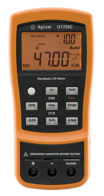 |
| My Agilent U1733C LCR Meter used for testing the BPF components. |
Referring to the schematic diagram again, you will see that each of the capacitor tuning nodes consists of up to two capacitors. This is necessary to achieve the overall capacitance value required that cannot be achieved with a single capacitor.
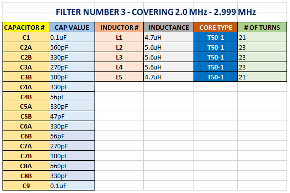
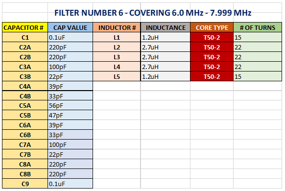
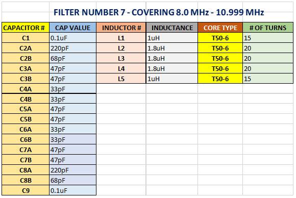
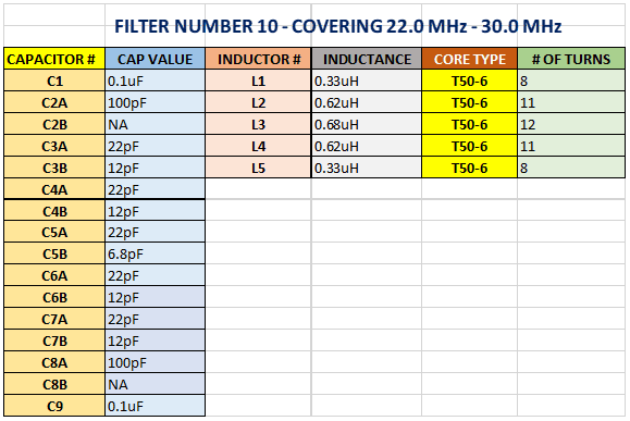
The following tables provide details of the inductor and capacitor values required to build each of the filters:
Please note filter number 1 has yet to be built and is not currently shown. Once this filter has been built I will update this blog post with the relevant table!
You may have noticed that the 0.56uH toroid inductors in filter #9 and the 0.62uH in filter #10 are both specified with 11 turns on T50-6 toroid cores. This is not an error the actual inductance is formed by altering the spacing between the windings on the core, ideally, this should be done with an LCR meter and the windings secured in place with a lacquer or an adhesive.
If you do not possess an LCR meter, the filter can still be built using the 5% tolerance components and fine-tuning the toroid inductors. This is done by altering the spacing of the coil turns around the core whilst monitoring the filter's pass band.
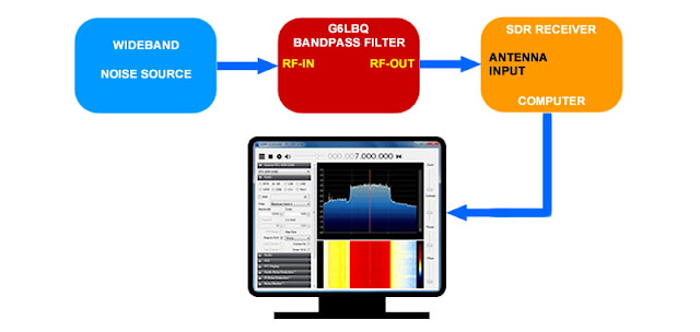
The pass band of the filter can be monitored with some simple inexpensive test equipment or a spectrum analyser with a tracking generator, though the latter is an expensive luxury. A simple but effective alternative is to use an SDR receiver in conjunction with a wide-band noise source. The following image illustrates how this is done:
A suitable SDR receiver is the RTL-SDR V3 USB dongle available for around £30.00
 |
Genuine RTL-SDR V3 Dongle |
https://www.rtl-sdr.com/buy-rtl-sdr-dvb-t-dongles/
Wide-band Noise Generators are easy to build and there are many schematics available on the internet. Alternatively ready-made modules can be purchased from the likes of eBay and AliExpress.
 |
Typical Noise Source Module available for around £20.00 |
There are various free software applications available that support the RTL-SDR dongles but my personal favourite is SDR# (SDRSharp) available from Airspy at the following web link:
So for around £50.00 you have what, in essence, is a poor mans spectrum analyser. This will also provide you with many hours of SDR listening pleasure 😉
I will leave it to the individual to setup and configure the software but if you do get stuck, there are lots of YouTube videos and guides available on the internet to assist you.
Finally to finish off the blog post, here is an image of the completed BPF (less the one remaining filter).
 |
G6LBQ High Performance HF BandPass Filter - 0.15MHz to 30MHz |
In
the next blog post, I will be building up the digital I/O board for my VFO, which will then allow me to control the BPF module. This module will also control the transmit LowPass filters that have yet to be developed.
NOTE: Once the I/O Board has been built & tested, I will then upload all of the VFO files to Groups.io!
As usual project files will be made available via the Groups.io platform by joining my G6LBQ community group, where you can discuss my projects, ask questions and help others.
Joining my group is free. Just click on the button below.
Until next time...








No comments:
Post a Comment
I appreciate your comments on the blog content, however the blog has been subject to idiots trying to use the comments facility as a means to post advertisements & spam so all comments are now approved and moderated.