In this blog post, I present an overview of the "Irwell HF Transceivers" vfo microcontroller software. It is intended as a guide to key features for those who have requested the software or are building the transceiver.
The software and MCU hardware are responsible for generating the VFO signal, oscillator frequencies and to provide control of the various transceiver stages.
The main VFO and controller hardware is based around an affordable STM32 Bluepill microcontroller board.
I presented the VFO & MCU hardware in a number of blog posts back in 2021 and these can be viewed by clicking on the following link.
For part 1 of the Digital VFO, click here.
It is fair to say a lot has happened since I designed the VFO controller back in 2021. Originally, my VFO hardware was very much developed around software I sourced & adopted from JA2GQP and JA2NKD.
Fast forward to 2023 and my project now has its very own software thanks to the fantastic work by my friend Dave... Thanks Dave, I will forever be in your debt!
Dave did a sterling job of structuring the software so that changes and additions could be made with relative ease and some basic programming knowledge. The new software has a simple menu system that permits adding new features and functions very manageable.
Adding new functions & features has unavoidably used up all of the STM32 Bluepills I/O pins but thankfully, Dave had the foresight to see this happening and written the software so switches attached to I/O pins can perform dual functions.
Whilst all of the Bluepill I/O pins are now in use, more I/O pins were made available via the STM32's two wire I2C bus.
The
VFO Oscillator PCB provides two I2C bus header connections via the Bluepill, one is used
to connect the I2C bus to the I/O extender board and the other is used
for connecting additional I2C devices, such as the PCF8574 I/O
Expander IC used to control the BHI DSP noise reduction module.
The main I/O expander board contains three PCF8574 ICs that are used to control the "Irwell HF Transceivers" bandpass filters, low-pass filters and modes of operation.
Each PCF8574 I/O Expander IC provides an additional 8 I/O lines and is configured with a hardware selectable hex address, these are then utilised by the software code to control all of the additional I/O lines the ICs provide.
The I/O Expander hardware is explained in more detail at the following blog link;
For part 5 of the Digital VFO, click here.
The original TFT Display and Bluepill MCU board produced in 2021 had just four function push switches, whereas the NEW 2023 board contains nine, with some performing multiple functions.
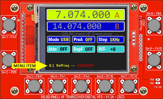
Here is an image of the 2023 display & microcontroller PCB.
The
above image was created from graphic elements, as I was unable to take an acceptable photograph of the TFT display without artefacts and poor colour representation.
Here is the same image with numbered finger pointers to aid in identifying each of the specific button functions.
A list of software functions associated with the
buttons is detailed as follows:
Button 1 has a single function to control the DSP noise reduction level. There are eight options available: OFF, 1, 2, 3, 4, 5, 6, 7 & Full - Each short press of the button increments the DSP level as specified on the display screen. A long press of the button reverses the increment level.
Button 2 has a dual function; a short press of the button toggles the receive RF Preamplifier ON or OFF - A long press of the button provides a shortcut into the vfo menu system PRESETS option - here you can operate the vfo rotary encoder to select from a list of pre-defined frequencies of interest.
Button 3 has a single function to control the receive attenuation level. There are four options available: OFF, 6dB, 12dB, 18dB - Each short press of the button increments the attenuation level as indicated on the display screen. A long press of the button reverses the increment level.
Button 4 has a single function to control and cycle through the various HF bands defined in the software. Each short press of the button increments the band selection, a long press of the button reverses the direction in which the bands are incremented.
Button 5 has a single function to set the mode of operation. There are currently five options available: FM, AM, CW, USB and LSB - Each short press of the button increments the mode of operation as specified on the display screen. A long press of the button reverses the increment direction.
Button 6 has a single function to set the vfo frequency step, there are seven options available: 1Hz, 10Hz, 100Hz, 1kHz, 10kHz, 100kHz, 1MHz - Each short press of the button increases the frequency step as specified on the display screen.
Button 7 has a single function to toggle between the VFO A frequency and VFO B frequency. VFO A is always the active frequency in use.
Button 8 has multiple functions associated to the receive RIT function. A short press of the button initiates a shortcut to the vfo menu system's RIT Offset - from here the vfo control knob is used to dial up a plus or minus receive frequency offset, a further short press of the button will exit the menu system and a long.press will cancel out the RIT Offset, returning it to a value of zero.
Button 9 has a single function and is used to enter the vfo menu system. A short press of the button calls up the menu
system and the VFO rotary encoder is used to scroll through the various menu
options that are available. To select a menu option, make a short press of the button again then
use the VFO rotary encoder to alter the menu items value. Once done, make
another short press of the button to exit the vfo menu system.
Menu items are displayed along the bottom of the screen as illustrated below.
Additional Features Available Through The Menu System.
The VFO menu system provides convenient access to some key setup options, which currently include;
- Calibration of the Si5351 25 MHz master reference oscillator.
- Setup of the LSB 11.059 MHz IF frequency.
- Setup of the USB 11.059 MHz IF frequency.
- Setup of the CW 11.059 MHz IF frequency.
- Setup of the AM 11.059 MHz IF frequency.
- Setup of the FM 11.059 MHz IF frequency.
- Setup of the 1st IF dual conversion oscillator. More on that as we progress.
It should be noted that the above IF frequencies can be changed to suit other crystal filter frequencies, just load up the appropriate menu and use the rotary encoder and frequency step button to make changes.
The VFO software supports the use of mechanical rotary encoders, optical encoders and hall effect rotary encoders. The more common mechanical rotary encoders typically provide around 24 pulses per rotation and operate with detent clicks when you turn them. This can be useful for some applications but is not ideal for VFO tuning applications. The optical and hall effect encoders provide a much smoother tuning experience. This is attributed to the higher number of pulses they produce per rotation and their ability to operate without detent clicks.
The rotary encoder I am using in my own build is the one shown on the left in the above image. This encoder produces 100 pulses per rotation and is silky smooth to operate. I purchased the encoder from Ali Express and it was delivered to my door at a cost of just over £10.00 in UK money.
NOTE: These encoders are designed to work with a DC supply voltage of 5-24V and use an internal voltage regulator. I found it necessary to link out the internal voltage regulator in order to get the encoder to function with the Irwell VFO.
When using high-resolution rotary encoders, the VFO software requires additional code to process the high number of pulses generated per rotation, failure to manage the pulses would result in a VFO that tunes way too fast.
Below is a section of the VFO software code that deals with defining the type of rotary encoder being used and its sensitivity.
Referring to the above image, it can be seen that line 26 is used to specify the type of rotary encoder being used. This line of code is commented out when using a mechanical encoder and uncommented when using high-resolution encoders.
If line 26 is uncommented; #define OPTICAL_ENCODER lines 28 and 29 are also processed by the software and used to set the encoder's sensitivity. A neat feature is the ability to set the sensitivity of the rotary encoder independently for the VFO tuning and menu operation.
If line 26 is commented out; //#define OPTICAL_ENCODER lines 31 and 32 are processed by the software and used to set the mechanical rotary encoders sensitivity.
The software for processing the rotary encoder does require additional code not covered here, which is beyond the scope of my general software overview.
Defining Some Preset Radio Frequencies
I have already touched on the preset radio frequencies when I detailed the operation of the VFO function buttons. Now it's time to look at how these are implemented and what options are available.
The preset frequency function is not to be confused with the memory store and recall facility typically found on commercial radio receivers and transceivers, it is just a list of favourite frequencies that are entered into the main software code.
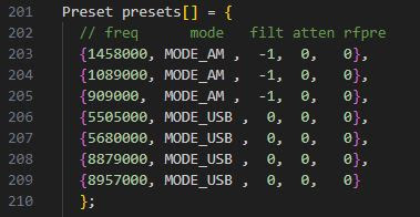
Below is a section of the VFO software code that deals with defining the preset frequencies and their options.
Referring to the above image, it can be seen that seven preset frequencies are listed between lines 203 to 209.
Each of the frequencies entered also requires the following options to be set;
mode Demodulation mode, AM, FM, USB, etc.filt Which of the main (11.059MHz) IF crystal filters should be used.
atten Set the receive attenuator level, OFF, -6dB, -12dB or -18dB.
rfpre Set the receive RF Preamplifier ON or OFF.
Preset frequencies can be added or removed by editing the software sketch, recompiling it and re-flashing the STM Bluepill.
Single Conversion & Dual Conversion Superhet Support
The VFO software has the ability to be used for both single & dual conversion superhet designs. This, in essence, means the VFO can be used for other radio and transceiver projects and not just the "Irwell HF Transceiver". The general structure of the VFO software is written so that features can be added or removed depending on the feature set required.
To set the superhet conversion type, several changes must be made to the software code before it is compiled and sent to the Bluepill module and these are shown in the following three images.
The superhet conversion be it single or dual, is set by commenting and un-commenting the lines of code as outlined in the comments. The above images show the code set for dual conversion.
It should be noted; the line numbers shown in all of the code illustration images may change with future software revisions. If you have received the software code and need to make changes, look for the blocks of code in the examples and do not rely on the code line numbers!
Important Information Regards Programming The STM32 Bluepill
The VFO software is written using the open-source Arduino platform and free IDE software, which is available on the official Arduino website.
The VFO software was written using version 1 of the IDE or version 1.8.19 to be more precise, there is a newer version 2 of the IDE but I have not tried this and so cannot confirm if all of the libraries and STM32 extension files are compatible, which may result in issues compiling the VFO software.
The STM32 Bluepill can be programmed several ways but the most convenient method is using the USB port located on the Bluepill module. The VFO software has been written to support this method but it does require the installation of a boot loader file onto the Bluepill prior to it being programmed with the VFO software.
There is also no native support for the STM32 Bluepill board in the Arduino IDE so it must be added using an Add-on package.
There is a useful guide on the Instructables website that can be followed to programme the boot loader into the Bluepill board and add the requisite support package to the Arduino IDE.
https://www.instructables.com/Programming-STM32-Blue-Pill-Via-USB/
The advantage of programming the Bluepill via its USB port is that software changes and upgrades can be carried out without having to strip down the transceiver or VFO.
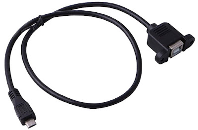
A short USB Micro B cable to USB B Female panel mount extension cable is used to make this possible, like the one shown below.
Note; Some software changes do not require the "get_version_id" value to be changed but if you are unsure, I suggest to increase the value as a matter of course. The value of the version id can be reset back to one by erasing the contents of the Bluepill and re-flashing the bootloader.
It is worth investing in an STLINK V2 USB dongle like the one shown below, as they are cheap to buy and can be used to erase the Bluepill and flash the bootloader.
The dongles are a clone of the genuine STMicroelectronics programmers but work extremely well and are reliable. The STMicroelectronics software ST Link Utility also works fine with these dongles and can be downloaded from the following web link.
Final Comments
This blog post serves as an overview of the key software features and is by no means a comprehensive breakdown of the software code.
The software has been in daily use for many months and has proven to be reliable and stable.
The software code is well commented to help assist with making changes, I regret I do not have the time to make changes to the software for individual user so please do not send me requests for doing so.
The code is supplied free of charge under the open-source licensing conditions, it is supplied with no guarantees or end-user support. You must not use the code for commercial gain without prior permission from the developer.
If you make any changes or additions to the code, please share these with me so they can be considered for inclusion into the main software code branch.
It should be noted that the software does not contain any code for CW keying, my intention is to build a dedicated hardware keyer independent to the transceiver's software.
Project files are generally available via the Groups.io platform by joining my G6LBQ community group, where you can discuss my projects, ask questions and help others.
Joining my group is free just click on the button below.
Until next time...


No comments:
Post a Comment
I appreciate your comments on the blog content, however the blog has been subject to idiots trying to use the comments facility as a means to post advertisements & spam so all comments are now approved and moderated.